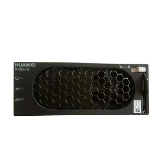
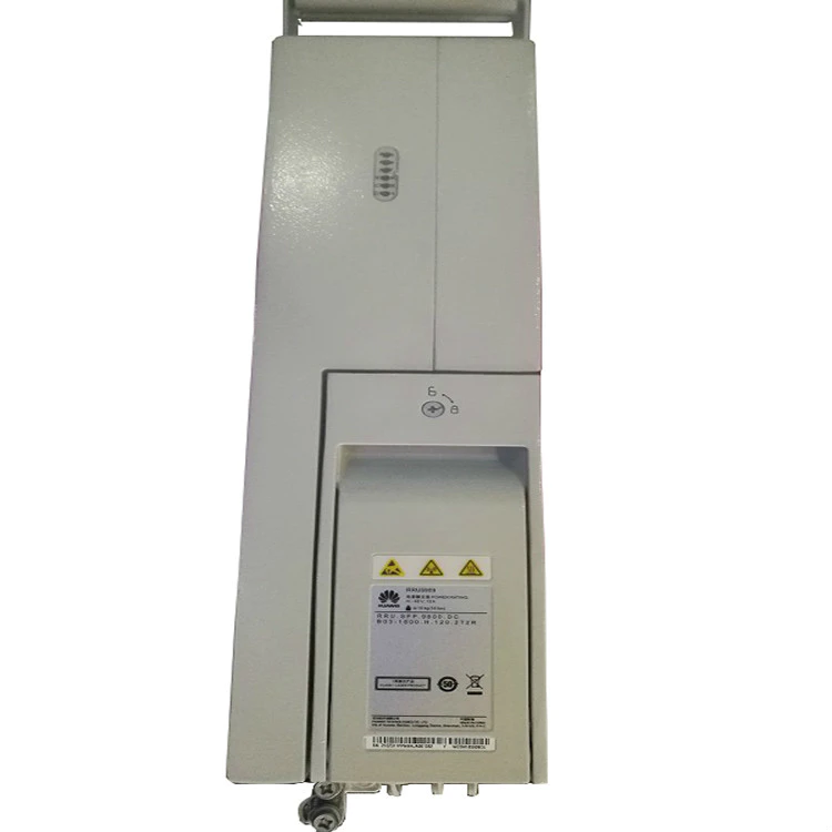
famous brand Hua-wei Communication Equipment RRU5818 8T8R 02312LWK
14 years optical transmitter,optical line terminal equipment,communication equipment experience

14 years optical transmitter,optical line terminal equipment,communication equipment experience
Product Overview
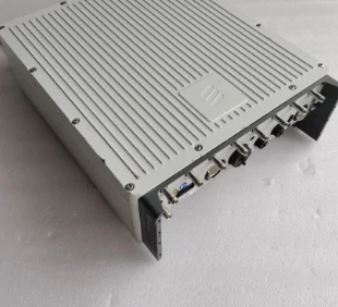
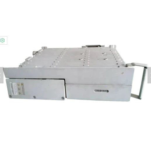
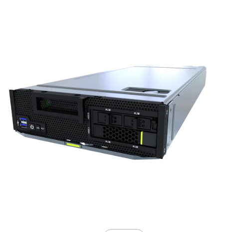
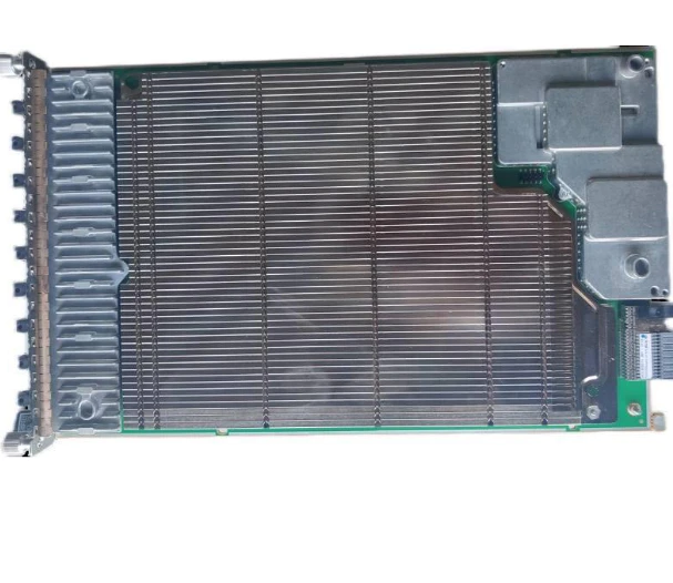
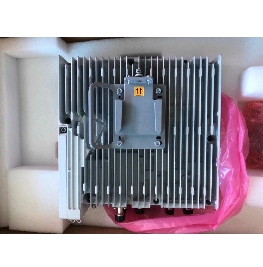
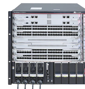
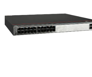
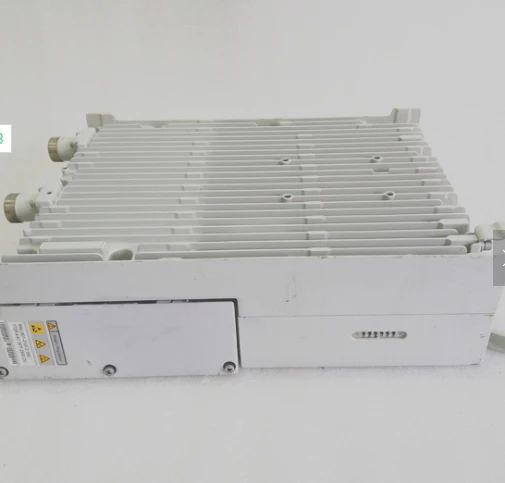
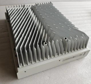
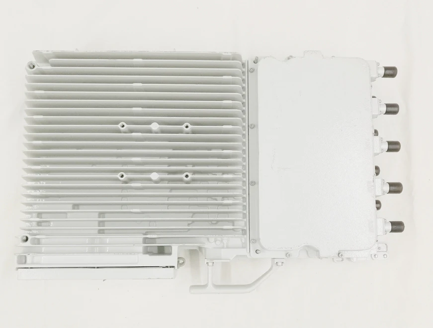
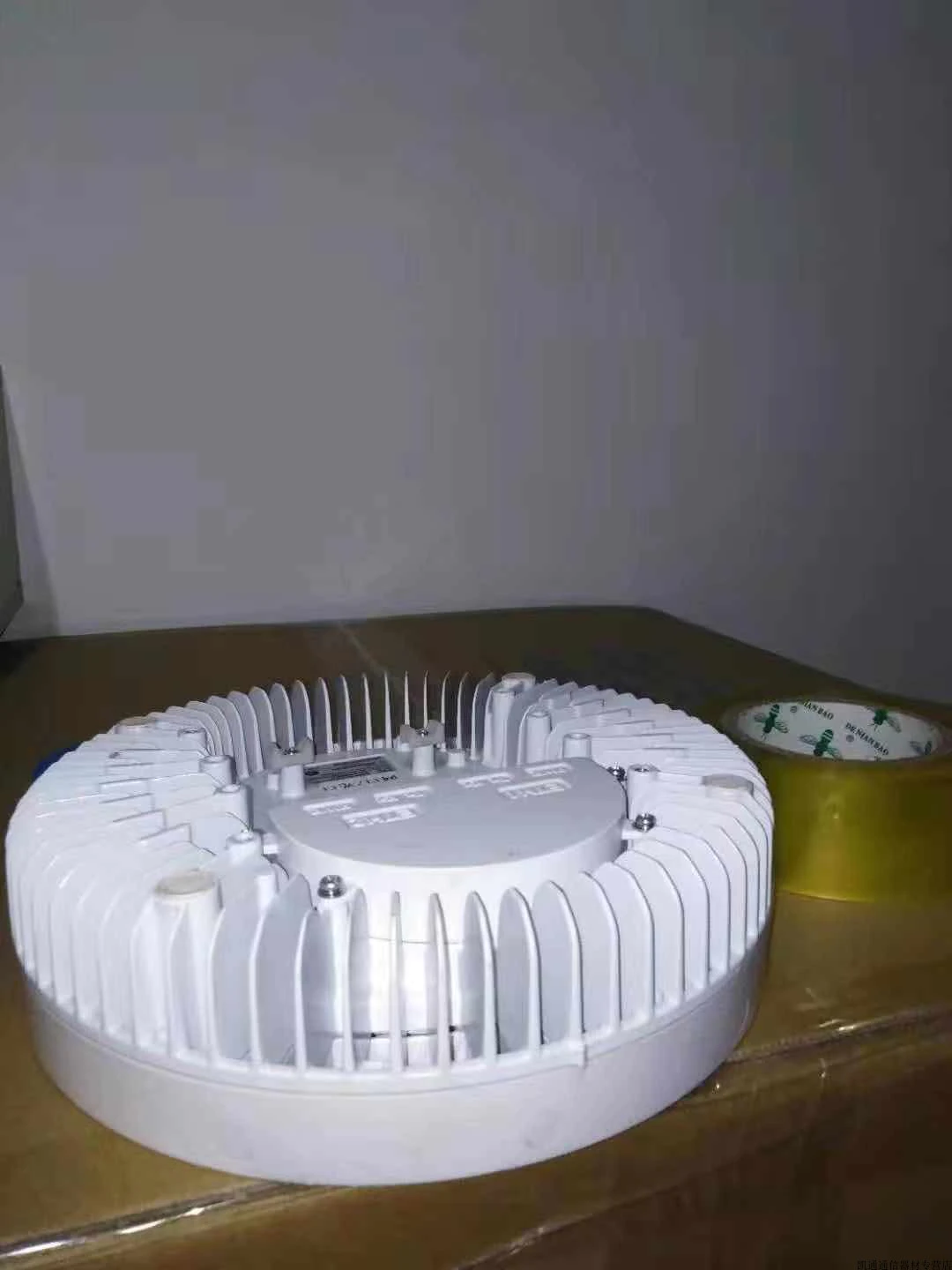
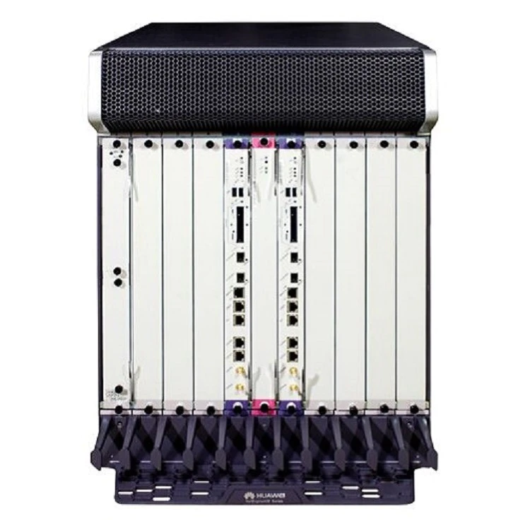
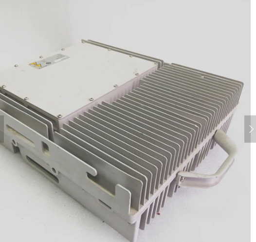
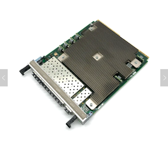
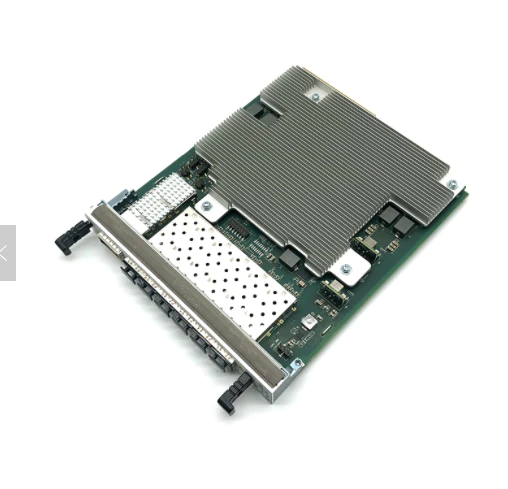
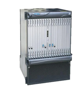
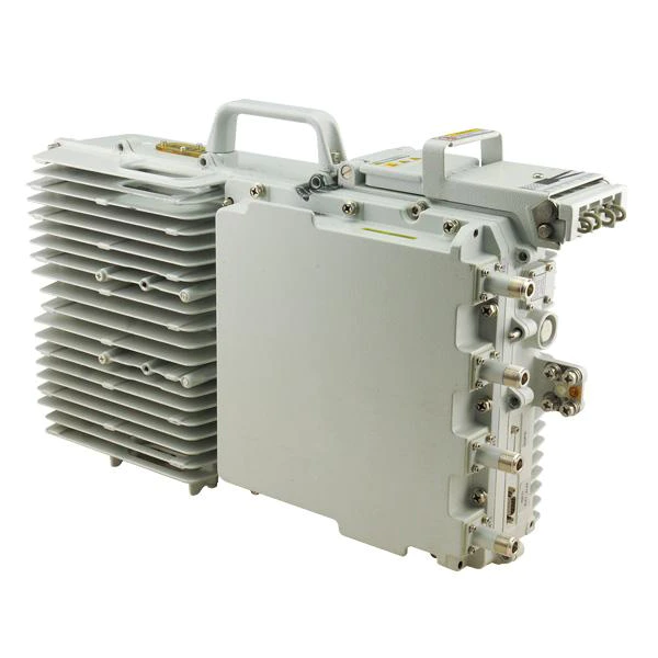
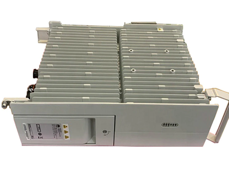
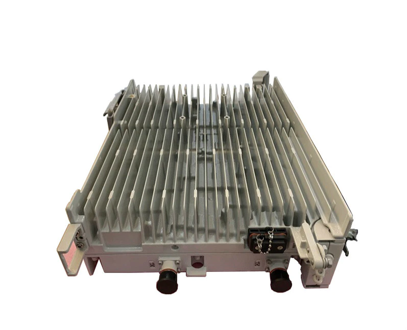
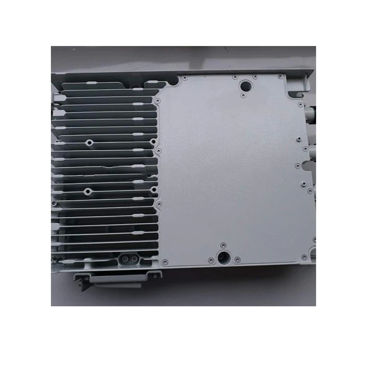
The RRU5909 is an outdoor remote radio unit which is powered by a power cabinet. It is the RF part of a distributed base station and can be installed near the antenna. The RRU5909 performs modulation, demodulation, data processing, and combination and division of baseband signals and RF signals. With the software-defined radio (SDR) technology, the RRU5909 can work in GU, GL, UL, or GUL dual mode through software configuration. The RRU5909 adopts a dual-transmitter and dual-receiver design, which further improves the output power and carrier capacity.
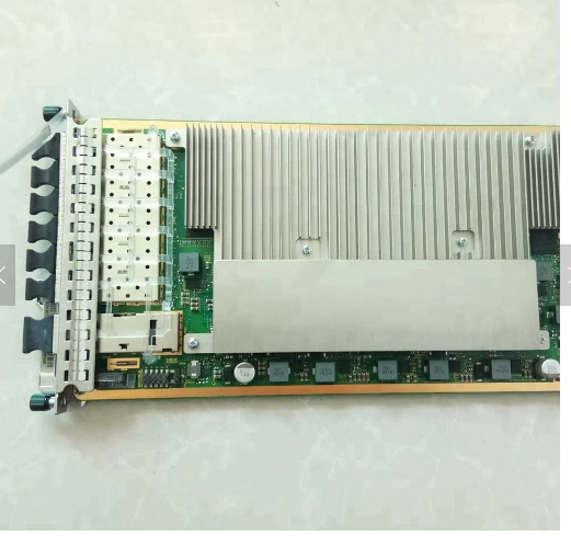
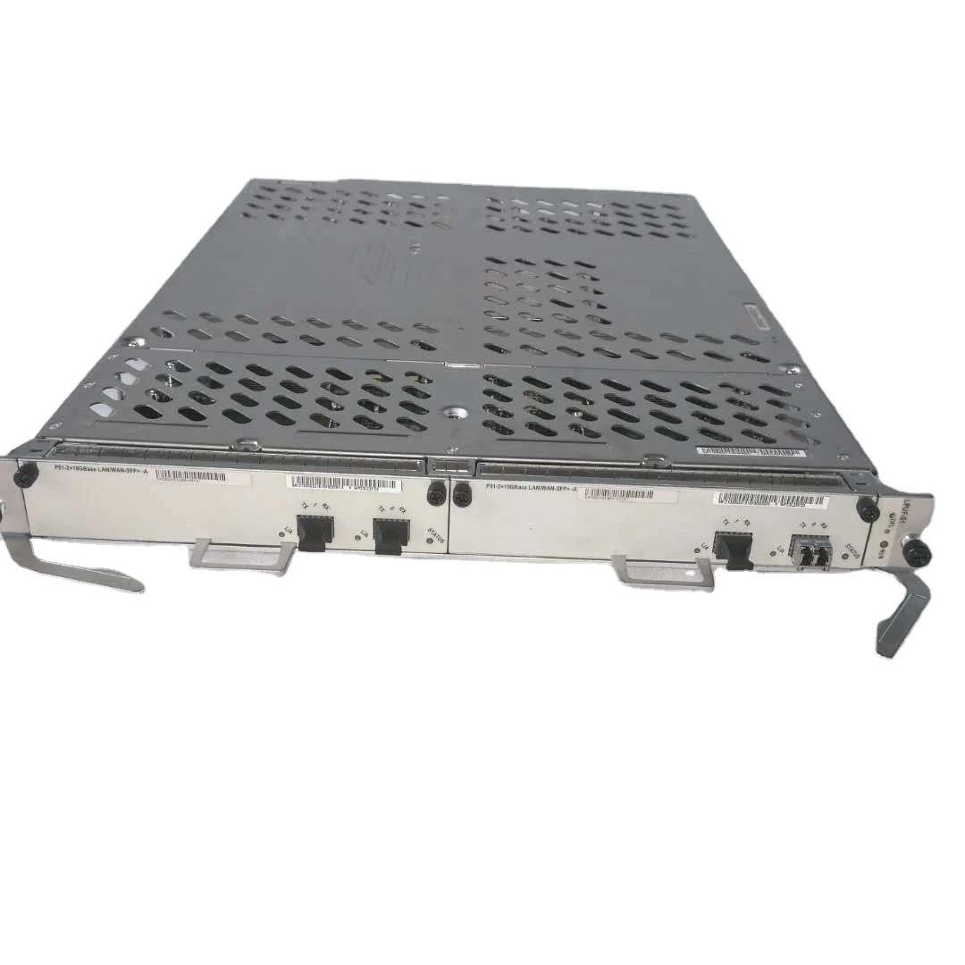
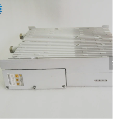
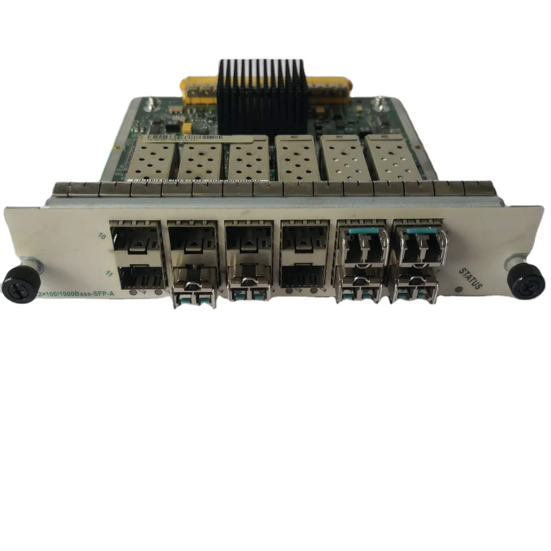
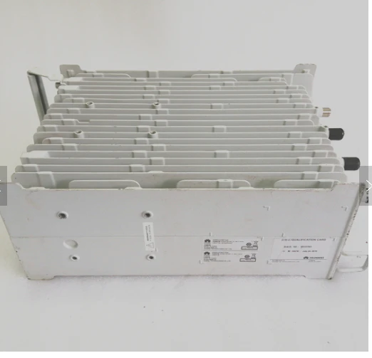
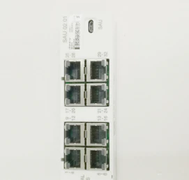
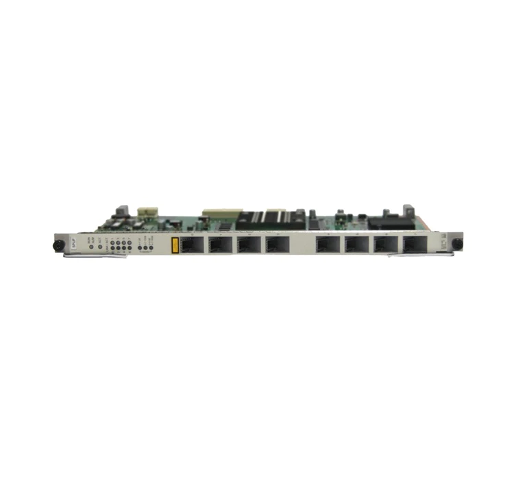
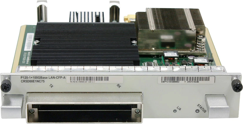
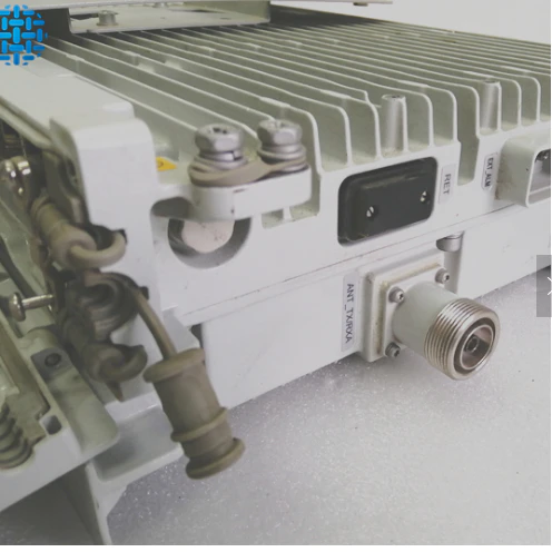
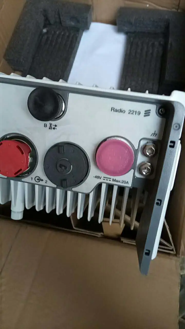
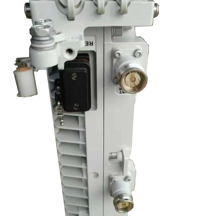
Physical Ports
The RRU has a modular design. Its external ports are located at the bottom of the module and in the cabling cavity.
Port | Connector | Quantity | Description |
RF port | 4.3-10 connector | 2 | Connects to the antenna system. |
CPRI port | DLC connector | 2 | Connects to a BBU. |
Power supply port | Tool-less female connector (pressfit type) | 1 | Supplies–48 V power. |
RET port | DB9 connector | 1 | Connects to a remote control unit (RCU). |
Frequency Band
Module | Frequency Band (MHz) | RX Frequency Band (MHz) | TX Frequency Band (MHz) | IBW (MHz) |
RRU5909
| 900 EGSM | 880 to 915 | 925 to 960 | 35 |
900 PGSM | 890 to 915 | 935 to 960 | 25 | |
1800 | 1710 to 1785 | 1805 to 1880 | 45 | |
2100 | 1920 to 1980 | 2110 to 2170 | 60 |
Capacity
Mode | Capacity |
GSM | (Supported only by the 900 MHz/1800 MHz frequency band) Each RRU5909 supports 8 TRXs. |
UMTS | (Supported only by the 900 MHz/2100 MHz frequency band) Each RRU5909 supports: •6 carriers without MIMO •4 carriers with MIMO |
LTE | Each RRU5909 supports 2 carriers and the LTE bandwidth can be 1.4 MHz, 3 MHz, 5 MHz, 10 MHz, 15 MHz, or 20 MHz. |
Power Consumption
The typical power consumption and the maximum power consumption are measured when the ambient temperature is 25°C.
The typical power consumption for GSM is measured when the load is 30%. The maximum power consumption for GSM is measured when the load is 100%.
The typical power consumption for UMTS is measured when the load is 40%. The maximum power consumption for UMTS is measured when the load is 100%.
The typical power consumption for LTE is measured when the load is 50%. The maximum power consumption for LTE is measured when the load is 100%.
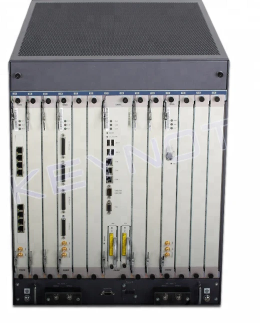
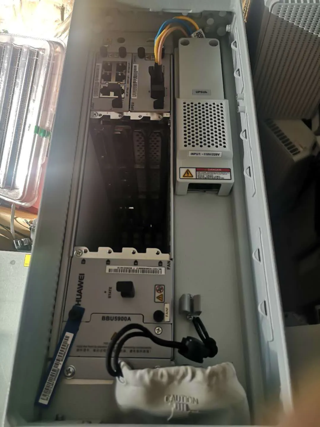
This section describes the power consumption of an entire base station. Board configurations in a BBU are as follows:
GSM: one GTMU board
UMTS: one UMPTb1 and one WBBPf3 boards in 3x1 and 3x2 scenarios; one UMPTb1 and two WBBPf3 boards in 3x3 and 3x4 scenarios
LTE FDD: one UMPTb1 and one LBBPd1 boards when one carrier is configured
Typical Output Power
An RRU5909 working in GSM mode and operating in the 900 MHz, 1800 MHz, or 2100 MHz frequency band complies with the EN 301 502 V9.2.1 standard. An RRU5909 working in UMTS, LTE FDD, or MSR mode and operating in the 900 MHz, 1800 MHz, or 2100 MHz frequency band complies with the ETSI EN 301 908 V5.2.1 and 3GPP TS 37.104 standards.
For the RRU5909 working in GSM mode, the maximum output power per carrier is 60 W when the S1 or S2 configuration is used. If the output power of 60 W is required, the corresponding power license must be purchased.
If an RRU5909 is located at an altitude of 3500 to 4500 meters, its power reduces by 1 dB. If an RRU5909 is located at an altitude of 4500 to 6000 meters, its power reduces by 2 dB.
Factors such as the inter-site distance, frequency reuse factor, power control algorithm, and traffic model affect the gains of dynamic power sharing. In most cases, network plans are designed based on the power specifications allocated by dynamic power sharing.
When the dynamic power sharing feature is activated, the power control and DTX functions must be enabled. In GBSS8.1, the dynamic power sharing feature is mutually exclusive with the GBFD-113201 Concentric Cell, GBFD-114501 Co-BCCH Cell, GBFD-118001 BCCH Dense Frequency Multiplexing, and GBFD-117501 Enhanced Measurement Report (EMR) features. In GBSS9.0 and later versions, the dynamic power sharing feature can be used together with these features. In GBSS8.1, GBSS9.0, and later versions, the dynamic power sharing feature cannot be used together with the GBFD-117002 IBCA (Interference Based Channel Allocation), GBFD-117001 Flex MAIO, GBFD-118701 RAN Sharing, and GBFD-114001 Extended Cell features.
Power sharing is performed on the assumption that UEs are randomly distributed in a cell.
The output power per carrier in the output power tables indicates the maximum output power supported to ensure network performance.
When two LTE FDD carriers are configured, it is recommended that the power spectrum density (PSD) be set to the same value for the two carriers. Power spectrum density = Carrier output power/Carrier bandwidth (1.4 MHz and 3 MHz bandwidths are considered as 5 MHz bandwidth in this formula.)
INQUIRY
Want more details please contact us
Copyright © 2019YANTAI YUNPAN INTERNATIONAL TRADE CO.,LTD. | All Rights Reserved
Hello, please leave your name and email here before chat online so that we won't miss your message and contact you smoothly.